
Hacking an Audi: performing a man-in-the-middle attack on FlexRay
{< video src="/img/hacking-an-audi-performing-a-man-in-the-middle-attack-on-flexray/image-01.mp4" >}
IntroductionPermalink
Last weekend comma.ai held a 48 hours hackathon at their San Diego office. We’ve seen some really cool projects, and hopefully the results will be upstreamed to openpilot soon. This post is about a project by three comma employees. The goal was to inject steering commands onto the FlexRay bus of an Audi as a proof of concept for adding openpilot support for a FlexRay vehicle.
Cars currently supported by openpilot communicate using a CAN bus. A panda is used to isolate the Lane Keeping Assist System (LKAS) camera, and proxies all the messages between the LKAS and the rest of the car. If we want to inject steering commands we can block specific messages coming from the LKAS and send our own.
FlexRay is a different communications protocol developed by a group of companies including Daimler, BMW, Motorola and Philips. It’s supposed to be faster and more reliable than CAN. It’s mostly used on more recent cars from European brands like Audi, BMW and Mercedes.
Compared to CAN, the FlexRay protocol is a lot stricter on timing. For example, the messages from all ECUs are sent on a fixed schedule: each ECU gets assigned time slots where they can send a message. On the Q8, the FlexRay bus has cycle time of 5 ms, so each ECU can send messages at 200 Hz.

Because the bus uses Time-Division Multiple Access (TDMA), the scheduling doesn’t allow receiving a message, changing certain bytes in the message, and then sending it out again at a random time.
To allow changing arbitrary data in a packet we have decided to modify individual bits in messages while they are transmitted over the bus.
Audi Q8 with Driver Assistance packagePermalink

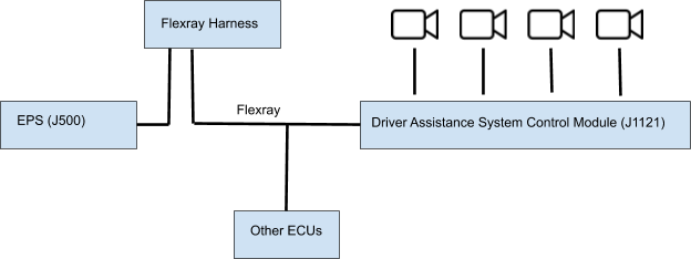
For this project, we decided to interrupt the FlexRay bus at the EPS side and place our proxy hardware between the EPS and the rest of the car. This way, we could make sure we could control everything that went into the EPS.
FlexRay Car HarnessPermalink
The comma two devkit interfaces with a vehicle using a car harness. We built a proof-of-concept that is a drop-in replacement for the car harness which utilizes an FPGA, four FlexRay transceivers and four CAN transceivers which could be considered a FlexRay car harness.
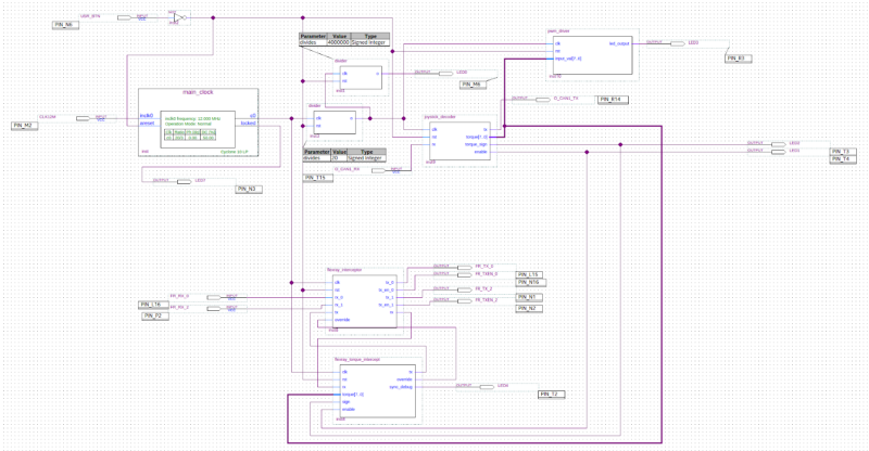
Conventional microcontrollers usually have custom silicon to handle transmission and reception of CAN and FlexRay messages. They receive the whole message, check the CRC and put the result in some registers ready for the end-user to use them. However, this does not allow manipulation on the bit level as required for this attack. Therefore, we decided to use an FPGA and implement the PHY (Physical Layer) for FlexRay ourselves.
The FPGA acts as a gateway or bridge between FlexRay and CAN. You send CAN messages to the FPGA, which stores the data received and overwrites the appropriate FlexRay bits when the message is transmitted on the bus. The FlexRay transceivers are used to split the FlexRay bus, and then proxy the messages between the two sides (allowing modification of messages on the fly).
Reverse engineering FlexRay messagesPermalink
The first step is to record the FlexRay messages from the stock system in order for us to analyze the messages and find which bytes control the steering.
Recording the messages on the FlexRay bus does not yet require the FPGA. We simply hook the outputs of the FlexRay transceivers on the FlexRay harness to a logic analyzer. We used the Saleae Logic Pro 16 analyzer which can do 500 MS/s, but any logic analyzer that can do 100 MS/s should be more than sufficient.
Decoding FlexRay messages by hand would be a lot of work. Unfortunately, the Saleae software does not include a FlexRay decoder. You can, however, write your own decoder, so we authored and open sourced a FlexRay decoder for Saleae logic analyzers.
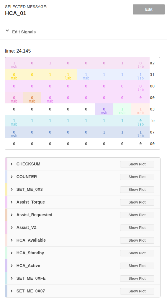
We went on several drives recording the vehicle in different states (manual steering, LKAS engaged vs. not engaged, LKAS steering left and right, etc…) and then combed through the data looking for the corresponding patterns. We found a frame with ID 65 that contained the LKAS steering control commands sent to the EPS. The steering data was in every fourth cycle and the last byte seems to be something like a sub-address. Interestingly, the data that we cared about very closely matched the CAN steering message HCA_01 already defined in opendbc for Volkswagen MQB vehicles.
Since openpilot already supports vehicles using this steering message, we know how to manipulate the bytes in the messages on the FlexRay bus to control the EPS even when LKAS is not active.
Modifying FlexRay messagesPermalink
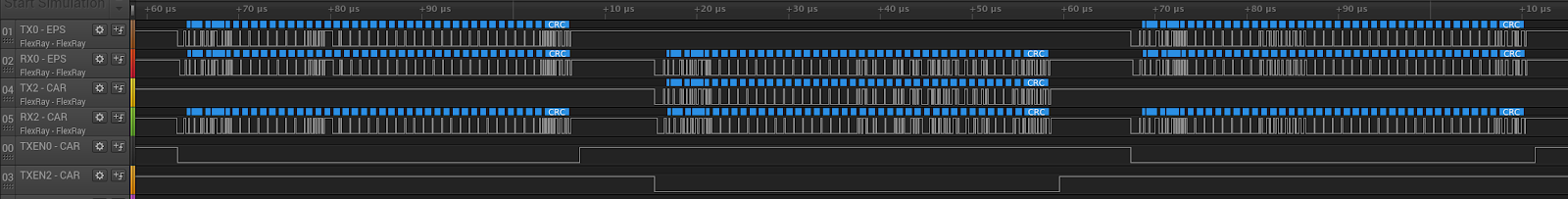
The first step is to split the bus electrically and proxy every message unchanged. In the FPGA we implemented a simple circuit that looks if there is data coming in from either side. Once the first bit comes in, we enable the transmitter on the other side and connect it to the receiver. After a frame is finished, there is a little bit of idle time on the bus and we can turn off the transmitter. Then this process starts from the beginning.
The following logic analyzer dump shows a packet coming from the car being forwarded to the EPS, then a packet from the EPS to the car, and then another packet from the car to the EPS.
The next step was to build a FlexRay packet decoder on the FPGA. Unfortunately there was no open source code available for this, so we had to write the VHDL code from scratch. We wrote a block that handles the reception of a single packet. Since most of the traffic is just forwarded we don’t need to handle any of the wake up and other types of special messages.
When the receiver matches a header with a certain frame ID and cycle counter, we change a couple bytes in the packet while forwarding. We also recompute the 24 bit FlexRay CRC on the fly and replace that too.
In the screenshot below you can see that we replace a few bytes in the message with Frame ID 65:
- Byte 24: checksum computed over byte 25 through 31
- Byte 25: a counter
- Byte 26: the requested torque
- Byte 27: sign of the torque, 0x80 when negative
- Byte 28: enable flags. 0x05 is enabled
- The 24 bit FlexRay frame CRC at the end of the packet

ConclusionPermalink
We built a python script to read a joystick and used a panda to send the CAN messages to the FPGA, which overrides the appropriate bits on the FlexRay bus to control the EPS. By combining the results from the previous steps, we were able to control the steering with a joystick.
This was only a proof of concept. To port a car, there is still quite a lot of work to be done. If you are interested in porting the first FlexRay car to openpilot and want to buy a FlexRay harness, contact support@comma.ai. If there is enough interest we can start selling them in our shop.
This project resulted in a two open source repositories which could be useful for anyone doing FlexRay research:
- FlexRay decoder for Saleae Logic: https://github.com/robbederks/FlexRayAnalyzer
- VHDL code for performing a man-in-the middle attack on FlexRay: https://github.com/pd0wm/flexray-interceptor
*Written by: Greg, Robbe and Willem
Join usPermalink
Do you want to work on projects like this? comma.ai is hiring!
If you want to see more of this follow us on twitter!
Leave a comment